• Welcome to RCTalk! 🚀

    Join the #1 RC community where hobbyists connect, share, and get expert advice on RC cars, trucks, boats, drones, and more!

    • Friendly & passionate RC enthusiasts
    • RC tips & troubleshooting
    • Buy, sell & trade RC gear
    • Share builds & upgrades

Welcome To "Learn Your Multimeter 101"

This site may earn a commission from merchant affiliate
links, including eBay, Amazon, and others.

Greywolf74

I'M TO BLAME!
Lifetime Supporter!
Supporter
Excellence Award
Hospitality Award
Build Thread Contributor RC Showcase: 8
Messages
18,623
Reaction score
14,482
Points
1,970
Location
Ohio
RC Driving Style
  1. Bashing
Just for the sake of those that need it and don't know it...

Welcome to learn your multimeter 101 :)

Probes: If your probes look like they are all plastic, then they have plastic caps covering the metal probes, and they have to be removed. (They just pull off)

th-3489861442.jpg


P-C11002___2___XL-3877929403.jpg


Blue Arrow = AC Voltage
Red Arrow = DC Voltage
Purple Arrow = AC milli-Voltage for low voltage AC
Yellow Arrow = Resistance (Ohms) but do not confuse this with the internal resistance of LiPo cells. They are not measured the same.
White Arrow = Continuity Testing. This would be for testing to make sure a circuit does not have a broken connection. For example, if you put one of the probes of the multimeter on one side of a fuse, and you put the other one on the other side of the fuse, then the multimeter will produce a tone if the fuse is good and the connection is not broken. If the fuse is blown, then there won't be a connection, and therefore you would not get a tone.
Don't worry about the other settings. You most likely won't use them if you don't already know how to use a multimeter.

If you have a lot more choices than above, then you do not have an auto sensing multimeter. These are typically older or cheaper models, but they work just the same. The whole section that is highlighted in yellow is for reading DC Voltages. The different selections move the decimal point around. For reading voltages between 0 - 4.2 volts you'll want the setting that says 20V if I recall correctly. If I happen to be wrong about that, then just set it wherever it puts the decimal point where you need it. The screen should look like this: "0.000" for reading individual LiPo cells.

EX310-2229500739.jpg


For reading the voltages of the individual cells, you'll want to set the multimeter to DC Voltage (red arrow). Once it's on the DC voltage, you will use the probes to read the voltage. Black probe on negative and red probe on positive. Don't worry if you get them backwards it won't hurt anything, it will just read the voltage and display a negative sign next to it. Reading the voltage of the main power lead should be obvious, but I'll explain the balance plug.

For the balance plug, you're going to measure the voltage of pin 1 and pin 2 for cell 1, pin 2 and pin 3 for cell 2, and pin 3 and pin 4 for cell 3. (See pics below)

For clarification:
Cell 1: Pin 1 & 2
Cell 2: Pin 2 & 3
Cell 3: Pin 3 & 4

Pin 4 should be a red wire. Doesn't matter what the color of the other wires is.

LiPoWiring-1588325567dabad.jpg

LiPoWiring-15883255SFBS67.jpg


LiPoWiring-15883255asdgas67.jpg


It's a bit of a tight squeeze to get the probes on the little silver tabs of the balance plug, but they will fit.

maxresdefault-198118560.jpg


Just make sure you don't touch the probes together when you're trying to get your readings!!!

ghostbusters-1551068348.jpg
 
Great write up thanks for posting this. They are not hard to use but there are a lot of ways to mess up too.

Black probe on negative and red probe on positive.
Just for clarity when you connect it to the DMM, you should using the port on the right denoted by V for Voltage. The one on the left is for Amps (current) and it probably wont do anything if you try to measure Voltage with it, which is just confusing. Not all probe sockets are red nor the same right/left orientation so match the symbols to the dial.
1726460584714.webp


I will add to this by saying you probably don't need a Fluke. Don't get me wrong it's a great tool and I actually own one. Bought it a long time ago and there weren't a lot of good alternatives at the time. But if it was now and I was buying a DMM I would skip the Fluke entirely.

They are not more accurate than most decent DMMs, the warranty is not better, they "might" be a little more rugged, but you would really have to beat on a DMM to get it to break.

The reason Fluke is the standard is they do not change the operation procedure or specification ever, even if the insides are different. That way if you are writing procedural documents that say push this button, turn this knob it's the same for ever for that model. Basically it's mil-spec.

If you really want the Fluke brand and only need to test basic things like batteries I would look at the 101. It's like $70 and just as accurate as the larger ones.
https://www.fluke.com/en-in/product/electrical-testing/digital-multimeters/fluke-101
Be prepared though, it's tiny. So don't drop it you might loose it in the carpet. It's so cute. 😍
NEWFLK101+(2).jpg
 
Great write up thanks for posting this. They are not hard to use but there are a lot of ways to mess up too.


Just for clarity when you connect it to the DMM, you should using the port on the right denoted by V for Voltage. The one on the left is for Amps (current) and it probably wont do anything if you try to measure Voltage with it, which is just confusing. Not all probe sockets are red nor the same right/left orientation so match the symbols to the dial.
View attachment 202482

I will add to this by saying you probably don't need a Fluke. Don't get me wrong it's a great tool and I actually own one. Bought it a long time ago and there weren't a lot of good alternatives at the time. But if it was now and I was buying a DMM I would skip the Fluke entirely.

They are not more accurate than most decent DMMs, the warranty is not better, they "might" be a little more rugged, but you would really have to beat on a DMM to get it to break.

The reason Fluke is the standard is they do not change the operation procedure or specification ever, even if the insides are different. That way if you are writing procedural documents that say push this button, turn this knob it's the same for ever for that model. Basically it's mil-spec.

If you really want the Fluke brand and only need to test basic things like batteries I would look at the 101. It's like $70 and just as accurate as the larger ones.
https://www.fluke.com/en-in/product/electrical-testing/digital-multimeters/fluke-101
Be prepared though, it's tiny. So don't drop it you might loose it in the carpet. It's so cute. 😍
NEWFLK101+(2).jpg
Good points here.

I did tell Majin in a PM that he just needs to grab any ole $20-ish DMM off of Amazon. Even if it isnt as accurate as a Fluke it will be close enough for hobby stuff :)
 
Good points here.

I did tell Majin in a PM that he just needs to grab any ole $20-ish DMM off of Amazon. Even if it isnt as accurate as a Fluke it will be close enough for hobby stuff :)
Agree 100% it is more than accurate for our hobby. Cause I don't really care if my voltage is 3.7500V or 3.7501V. Also they are probably 2x more accurate than a battery checkers.

Save that money and buy a good solder station and good set of hex drivers.
 
Save that money and buy a good solder station and good set of hex drivers.
☝️ THIS! A quality soldering station and hex drivers are soooo important. It pains me when I see people buy cheap ones and then have to turn around a short while later and buy it again.
 
Next up: Using an Oscilloscope for RCs.
Yes please! I have always been a little curious about oscillioscopes, but never really took the time to learn about them.
 
Yes please! I have always been a little curious about oscillioscopes, but never really took the time to learn about them.

There have been books written on this, so here is the 2 min read.

In a nut shell the Oscilloscope (AKA Scope) shows voltage (vertical) vs time (horizontal) . Each are scaled by the knobs denoted by the V and T below.
1726639462309.webp


This is a two channel scope (yellow and pink) and the scope lead attaches to the BNC connector below it. There are two V knobs one for each channel (CH1, CH2).

On the bottom of the screen you can see your units of time and voltage.

That refers to the value per grid (vertical or horizontal)
1726641608226.webp
. For instance you see channel 1 in yellow has a value of 1V per grid (square). If you look at the yellow signal and count the squares, it's about 2.1V in amplitude. Each channel can have a different voltage level but they must have the same time value.

The horizontal grid is the time axis and has a value shown of 500us (5E-10). Which means the same yellow signal has a frequency of 1000us or 1Hz. Also shown at the bottom, with a lot of trailing 0's.

The row of three knobs on the bottom moves the signals up/down on the screen for each channel (yellow/pink). You can move CH1 on the bottom and CH2 on the top, or overlay them.... whatever you like. The lower knob on the right allows you to scroll backwards and forwards in time, because not all signals are repetitive.

The
1726639917114.webp
at the top is the trigger time (time 0), and the markers (
1726639949734.webp
,
1726639958955.webp
) on the left are the voltage at the trigger point. At the bottom of the screen you see
1726640059306.webp
. That is the voltage for CH1 at the trigger point (Time 0).

So with that in mind it means that waveform on CH1 is actually about +/- 1.05V.
Probably the most important button
1726640174633.webp
.This will automatically find the signal and adjust the scale so it's readable. It's a starting point.for when you get all messed up and you will.

1726640293216.webp
This is a spec of the scope. It means that it can effectively display signal with a frequency up to 150 MHz by sampling it 1 billion times per second. If you try to measure something faster it will smooth it out and you will be missing the detail required.

This is a USB port. :p
1726641002970.webp


There are a lot of other very cool things you can do with it too. Look at things in time domain, measure current. measure sound, noise, frequency, export the image, connect it to a network and us your computer display, persistent sampling and lots more. You can get one with more channels, more bandwidth and lots of accessories.

Most modern scopes have relatively low voltage input of around 5V or less. Check the spec and be careful to use the correct probes so don't blow it up.

It is the Shopsmith of electronics.
1726641286939.webp
 
There have been books written on this, so here is the 2 min read.

In a nut shell the Oscilloscope (AKA Scope) shows voltage (vertical) vs time (horizontal) . Each are scaled by the knobs denoted by the V and T below.
View attachment 202751

This is a two channel scope (yellow and pink) and the scope lead attaches to the BNC connector below it. There are two V knobs one for each channel (CH1, CH2).

On the bottom of the screen you can see your units of time and voltage.

That refers to the value per grid (vertical or horizontal)View attachment 202760. For instance you see channel 1 in yellow has a value of 1V per grid (square). If you look at the yellow signal and count the squares, it's about 2.1V in amplitude. Each channel can have a different voltage level but they must have the same time value.

The horizontal grid is the time axis and has a value shown of 500us (5E-10). Which means the same yellow signal has a frequency of 1000us or 1Hz. Also shown at the bottom, with a lot of trailing 0's.

The row of three knobs on the bottom moves the signals up/down on the screen for each channel (yellow/pink). You can move CH1 on the bottom and CH2 on the top, or overlay them.... whatever you like. The lower knob on the right allows you to scroll backwards and forwards in time, because not all signals are repetitive.

The View attachment 202752 at the top is the trigger time (time 0), and the markers (View attachment 202753, View attachment 202754) on the left are the voltage at the trigger point. At the bottom of the screen you see
View attachment 202755. That is the voltage for CH1 at the trigger point (Time 0).

So with that in mind it means that waveform on CH1 is actually about +/- 1.05V.
Probably the most important button View attachment 202756.This will automatically find the signal and adjust the scale so it's readable. It's a starting point.for when you get all messed up and you will.

View attachment 202757 This is a spec of the scope. It means that it can effectively display signal with a frequency up to 150 MHz by sampling it 1 billion times per second. If you try to measure something faster it will smooth it out and you will be missing the detail required.

This is a USB port. :p
View attachment 202758

There are a lot of other very cool things you can do with it too. Look at things in time domain, measure current. measure sound, noise, frequency, export the image, connect it to a network and us your computer display, persistent sampling and lots more. You can get one with more channels, more bandwidth and lots of accessories.

Most modern scopes have relatively low voltage input of around 5V or less. Check the spec and be careful to use the correct probes so don't blow it up.

It is the Shopsmith of electronics.
View attachment 202759
Yup. As I always thought, way above my pay grade. Thanks for the breakdown, but I have no idea what any of that means, or what the info the oscilloscope gives you is used for. @Greywolf74 might find that useful though.

My dad had a Shopsmith with every possible attachment you could get for it. Awesome piece of equipment for small jobs 😉
 
I've often thought about messing around with an oscilloscope before, but I'm not sure how it would be useful for RC exactly. I'm not sure what I would use it for period, actually.
 
You could spend several hundred or thousand of dollars to measure DC battery voltages.

The only thing I can think of is looking at the receiver channel outputs and analyzing the pulse widths. But unless you are building a radio, receiver, servo etc there is no reason to.

So save your money.
 
Good points here.

I did tell Majin in a PM that he just needs to grab any ole $20-ish DMM off of Amazon. Even if it isnt as accurate as a Fluke it will be close enough for hobby stuff :)
Arriving tomorrow by 10 PM
Shipped
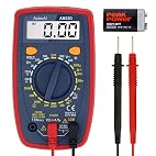
AstroAI Multimeter Tester 2000 Counts Digital Multimeter with DC AC Voltmeter and Ohm Volt Amp Meter ; Measures Voltage, Current, Resistance; Tests Live Wire, Continuity
i listen so i can learn lol

Agree 100% it is more than accurate for our hobby. Cause I don't really care if my voltage is 3.7500V or 3.7501V. Also they are probably 2x more accurate than a battery checkers.

Save that money and buy a good solder station and good set of hex drivers.
when i got a set of mip i was blown away. till then i just thought i deened lots of back up screws.. never again made wrenching a not as scary practice then an enjoyable one
 
Back
Top