Greywolf74
I'M TO BLAME!
Lifetime Supporter!
Supporter
Excellence Award
Hospitality Award
Build Thread Contributor
RC Showcase: 8
This build is looking really nice man! 

Follow along with the video below to see how to install our site as a web app on your home screen.
Note: This feature may not be available in some browsers.
Join the #1 RC community where hobbyists connect, share, and get expert advice on RC cars, trucks, boats, drones, and more!
My very first car was a 65 Mustang. It was missing the grille bars in the front grille that extend off each side of the horse corral in the center, and I was too poor to buy new ones, even if I could find them.Nothing better than sitting in the shop on a Sunday morning. Just tinkering with my drag car.
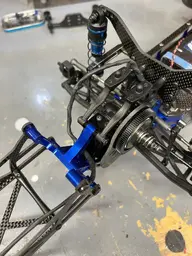
I was thinking about how the tires expand and rub the body. I have belted tires but I don’t want the ugly black half moons so I covered the inside with aluminum. It’s tape for duct work and it’s .02mm thick. Has a nice glue on like a sticker.
The cool thing is it’s so thin you can rub out wrinkles with you thumbnail. I am going to bet you could use this stuff to cover panels on the outside. And polish it or make it look like metal.
It wraps around corners and sticks pretty well. The writing comes off with alcohol.
I’m going to mess with this stuff today.
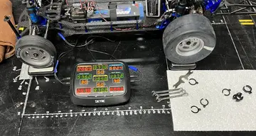
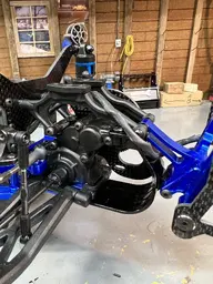
Good idea with the power on rain light. Be good for night events and days with limited visibility 132ft down range.I put a red LED on the wheelie bar. Just for visibility and so I know if I have the radio turned on.
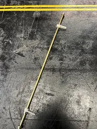
It’s just a rod end with the 5mm LED held in place with an O ring and some glue.
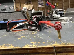
Personally I would not suggest using lead free solder. Not that you can't make it work but its harder to work with, its more expensive, It hardens with a dull look so it makes it harder to tell how much oxidization is in your solder joint, and the higher temps needed to melt lead-free solder comes with significant component stress; therefore, low dielectric components are more vulnerable to failures. Lead-Free also has lower "wettability". Low wettability makes the solder joint function ineffectively in meeting the demands of self-regulation ability, tensile power, and shear capacity. Consequently, low wettability causes a high rejection rate of solder joints, especially when you fail to conduct adjustments to cater to this shortcoming.I have a 30 watt soldering iron. I would like to use lead free solder because of the higher melt point than lead. And the wiring are already tinned with lead free. My cheep 30 watt soldering iron won’t melt the lead free solder and trying lead solder made a crumbly alloy and That made a mess of things. I got them soldered but it is totally unacceptable cold solder.
I’m going to need a 70-100 watt soldering iron for get enough heat quickly enough to properly solder heavy 10 gauge wires.
")
")
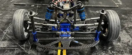
I've been wondering about these types of conversion chassis and whether or not it would be better to use one or just order a dedicated kit.I have to order some 4mm bullet connectors that have a nail shape head.
And I have more 10AWG wiring coming with 6.5mm ends pre soldered so all I have to do is the motor.
I also found the proper linkage for the steering.
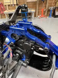
I think I’m almost to the point that I might as well replace the control arms and put together a stock DR10 from all the parts.