OK. Home from work, I'll take ya into the carrier. I'm not going to bore you all with the whole process of downsizing this thing, but I will show why I chose to do so. These are the styrene decks, old and new. You can see by the difference in size how out of proportion that big one is to the new, unpainted one. The original cab is used, with some mods. The verdict is still out on the hood (just set on there for now).
View attachment 121624
Reducing the carriers size does not make the crane any less stable when in operation, because the foot print of the outriggers remains the same with them all extended.
The carrier as it looks now.
View attachment 121625
It will have diamond plate fenders similar to those on the original.
Guts.
View attachment 121626
That motor you see is not the drive motor. It is connected to a mechanism that lifts the counterweights into position to set on upper unit. This model is capable of self assembling like a real one. you set the weights on the carrier deck with the crane, actuate the lift, swing the upper into position, and then set the counterweights on their platform. I saw that on a real crane and HAD to make it work!
The ESC runs the six motors that also comprise the axles.
View attachment 121627
Two motors are stuffed into a bored-to-fit ABS pipe fitting, shaft out. The shaft is clamped into a hub and the rims, again from those aluminum cylinders I scrounged. wired accordingly. Those assemblies are clamped into aluminum rocker arm setups that keep the weight on all 6 axles equally and allow it to take undulations in the ground surface. The gear motor speed is "yard speed", it tops at around 10 mph maybe, but it allows for very slow creeping and positioning very smoothly.
Steering, front suspension: You guys get steering components and angles so I'll let the pix do most the talking here.
View attachment 121628
View attachment 121629
View attachment 121630
View attachment 121631
The axles and spindles were machined from brass bar, with some pieces turned from round solid brass bar. The suspension subframe is sheet brass. It is a walker beam from front to rear and equalizes over the front and rear axle. The center has enough spring added by those flat leaf springs to keep is planted on the ground. Like the rear, it can take uneven ground. Not like a rough terrain crane, but anything a 6 axle unit should be able to handle. Note in the top picture that the servo box is mounted horizontally, the arm actuates Pittman style. The 3 are linked progressively to maintain pretty close to Ackerman geometry on all 3.
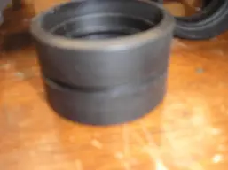
Tires were a major challenge on this downsizing project. The originals were pirated from ERTL Payhauler 350 dump truck kits. 18 tires. They were really too big. Nobody makes the size I needed. I finally decided to use black ABS pipe fittings and 1/4 inch ABS sheet to scratch build them. With some trial and error, well, look: one of the 6 dually sets.
View attachment 121633
Two tires were turned into each pipe joint together for the rear duals. Later ridges were turned in the tread part to hold rubber treads cut from bicycle inner tubes for traction. You can see that in the front tires in previous pictures. The side walls were made from the sheet abs, and contoured on the lathe before inserting and gluing into the fittings. They were all made to fit the original rims, as they were already how I liked them. that saved a lot of work.
The receiver and 4 of the 7 Nimh batteries, again cut out of a new 8.4, are in that box under the frame. 2 cells are between the two forward-most rear tires, and one is in the fuel tank. Space is at a premium on the carrier too! I have to just gulp and start cutting the battery packs apart. You know what that does to the warranty

I can answer any questions you may have on any of the above if you like. The project still has a way to go, but I'm on the downhill side of it now. Thanks for following. Dan